
Page 182 [182]
cas A NI 7
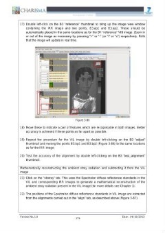
17) Double left-click on the B3 “reference” thumbnail to bring up the image view window
containing the IRR image and two points, B3.apl and B3.ap2. These should be
automatically placed in the same locations as for the D1 “reference” VIS image. Zoom in
or out of the image as necessary by pressing “+” or “-” (or “i” or “o”) respectively. Note
that the image will update in real time.
T *F:\ Technical Imaging\ John Cupitt\zip files\bm4\bm-workspaces2.ws - align -lo)>
Elle Edit View Tookits Help
| input linear markup | viscalib | uvicalib | align | specden falsecolour uvistray uvkm_ vilstray vikm | results +
A — ¬
B3.adjust - 17.
Help
923888 32-bit float, 3 bands, XYZ, 115.33 MB, 9.45x9.45 pimm
1.75007 1.84127 2.00482 Magnit
B2
CLP LD ECD
ante B
Match, default 026 023.targets B1.targets
—n BD
a earch Desktop (0S OO SG 118
18) Move these to indicate a pair of features which are recognisable in both images. Better
accuracy is achieved if these points as far apart as possible.
19) Repeat the procedure for the VIL image by double left-clicking on the B3 “adjust”
thumbnail and moving the points B3.bp1 and B3.bp2 (Figure 3-86) to the same locations
as for the IRR image.
20) Test the accuracy of the alignment by double left-clicking on the B3 “test_alignment”
thumbnail.
Mathematically reconstructing the ambient stray radiation and subtracting it from the VIL
image
21) Click on the “vilstray” tab. This uses the Spectralon diffuse reflectance standards in the
VIL and corresponding IRR images to generate a mathematical reconstruction of the
ambient stray radiation present in the VIL image (for more details see Chapter 1).
22) The positions of the Spectralon diffuse reflectance standards in VIL image are extracted
from the alignments carried out in the “align” tab, as described above (Figure 3-87).
Version No. 1.0 174 Date : 14/10/2013