
Oldal 180 [180]
10)
11)
12)
13)
14)
{3} *F:\ Technical Imaging\ John Cupitt zip files\bm4\bm-workspaces2.ws - align
Eile Edit View Toolkits Help
| input linear markup | viscalib wate [do] specaen falsecolour uvistray uvikm vilstray vikm | results +
Eile View Help
S| 81 | tinear.k9 Image, 2592x3888 32-bit lost, 3 bands, XYZ, 115.33 MB, 9.45x9.45 pimm
(2591, 3684) _2.20055_2.98644_2.80434_Magnifcation 1:6)
apl JMárkonB2ireférencs ak (2046; 1492)"
ap2 JMarkonBzireference at (2264, 2504)
bp | Marken Bassist at (2056, 1498)0
bp2 | Markan Baad a (2278; 2988)
Match default 026 023.targets B1.targets
PRP RERSE EBS
test_alignment
Si
eae 83
ee reference
=,
adjust
vy
Ic : [mm om
Bsat| 6B 0) ohn.) Bul fle.) Or] Swi] Bef Et [elv] Pv] Ben] Wo. MH a [dt Dexter [98 UO BA 1126
Figure 3-83
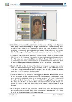
As with the previous workflow, alignment is carried out by selecting a pair of points in
each image. The corresponding VIL images are rotated and scaled according to the
position of these points in the corresponding images until these are aligned. The VIS
images in the “reference” thumbnails are automatically carried over from the “viscalib”
tab. The VIL images in the “adjust” thumbnails are carried over from the “linear” tab.
To align the Spectralon diffuse reflectance standards in the VIS and VIL images, double
left-click on the B2 “reference” thumbnail to bring up the image view window containing
the VIS image and two points, B2.ap1 and B2.ap2 (Figure 3-83). These should be
automatically placed in the same locations as for the D26 “reference” VIS image. Zoom
in or out of the image as necessary by pressing “+” or “-” (or “i” or “o”), respectively.
Double left-click on the B2 “adjust” thumbnail to bring up the image view window
containing the corresponding VIL image. Move the points B2.bp1 and B2.bp2 (Figure
3-84) to the same locations as for the VIS image. It may be useful to have the window
containing the VIS image open simultaneously.
The points are moved by left-clicking and dragging on the label. Move these to indicate
a pair of features on the standards which are recognisable in both images. Better
accuracy is achieved if these points as far apart as possible. Note that it is not essential
to use the standards themselves for the alignment (which may be difficult if, for example,
the image is quite dark), as long as these are correctly aligned in both images. The
image will update in real time, which may cause a Slight response delay in larger
images.
If the image is too dark or light, click View > Toolbar and check the “Display Control”
box. This will bring up a slider which allows the brightness to be adjusted. This change
is purely for visual purposes and will not alter the data.
172