
OCR
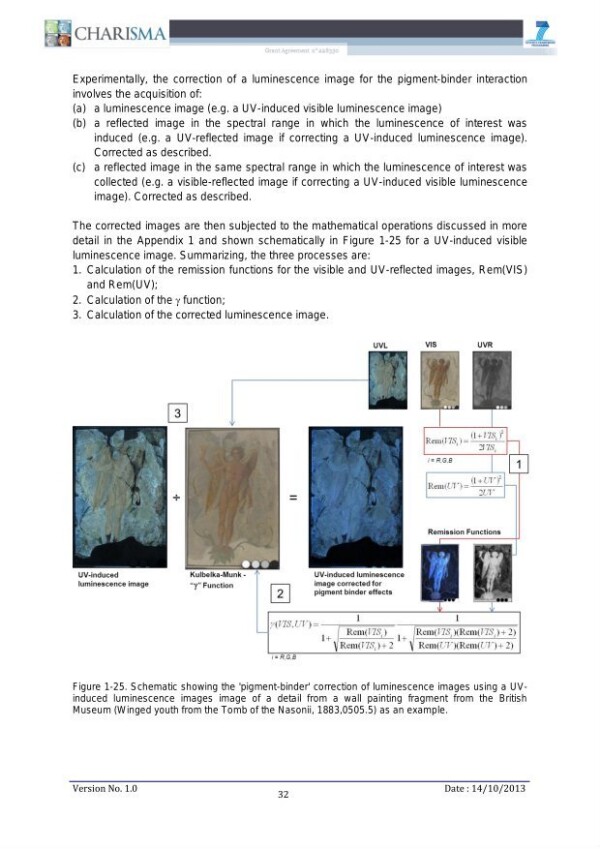
Bc A BR 7 ent n" 228 Experimentally, the correction of a luminescence image for the pigment-binder interaction involves the acquisition of: (a) a luminescence image (e.g. a UV-induced visible luminescence image) (b) a reflected image in the spectral range in which the luminescence of interest was induced (e.g. a UV-reflected image if correcting a UV-induced luminescence image). Corrected as described. (c) a reflected image in the same spectral range in which the luminescence of interest was collected (e.g. a visible-reflected image if correcting a UV-induced visible luminescence image). Corrected as described. The corrected images are then subjected to the mathematical operations discussed in more detail in the Appendix 1 and shown schematically in Figure 1-25 for a UV-induced visible luminescence image. Summarizing, the three processes are: 1. Calculation of the remission functions for the visible and UV-reflected images, Rem(VIS) and Rem(UV); 2. Calculation of the y function; 3. Calculation of the corrected luminescence image. UVR 3 .. (L478. Rem(7S,)=! a — J ais, | | iz R.GB 1 r\2 Remy) - Et ) 2UV Remission Functions UV-induced Kulbelka-Munk - UV-induced luminescence luminescence image "ey" Function image corrected for 2 pigment binder effects ee 1 1 y(VIS,UV) Rem(I7S ) 1 Rem(I7TS ((Rem(TIS ) -- 2) Rem(ITS ) + 2 Rem(UTX(Rem(UT)-- 2) iz RG B Figure 1-25. Schematic showing the 'pigment-binder' correction of luminescence images using a UVinduced luminescence images image of a detail from a wall painting fragment from the British Museum (Winged youth from the Tomb of the Nasonii, 1883,0505.5) as an example. Version No. 1.0 32 Date : 14/10/2013
Strukturalno
Custom
Image Metadata
- Širina slike
- 2481 px
- Visina slike
- 3508 px
- Rezolucija slike
- 300 px/inch
- Veličina originalnog fajla
- 1.22 MB
- Permalink ka JPG-u
- srb_000007/0039.jpg
- Permalink ka OCR-u
- srb_000007/0039.ocr
