
OCR
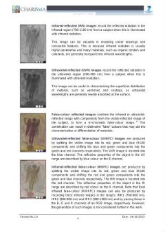
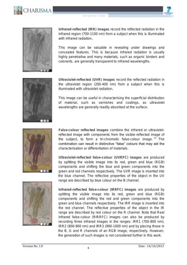
Infrared-reflected (IRR) images record the reflected radiation in the infrared region (700-1100 nm) from a subject when this is illuminated with infrared radiation. This image can be valuable in revealing under drawings and concealed features. This is because infrared radiation is usually highly penetrative and many materials, such as organic binders and colorants, are generally transparent to infrared wavelengths. Ultraviolet-reflected (UVR) images record the reflected radiation in the ultraviolet region (200-400 nm) from a subject when this is illuminated with ultraviolet radiation. This image can be useful in characterising the superficial distribution of material, such as varnishes and coatings, as ultraviolet wavelengths are generally readily absorbed at the surface. False-colour reflected images combine the infrared or ultravioletreflected image with components from the visible-reflected image of the subject, to form a tri-chromatic false-colour image." The combination can result in distinctive “false” colours that may aid the characterisation or differentiation of materials. Ultraviolet-reflected false-colour (UVRFC) images are produced by splitting the visible image into its red, green and blue (RGB) components and shifting the blue and green components into the green and red channels respectively. The UVR image is inserted into the blue channel. The reflective properties of the object in the UV range are described by blue colour on the B channel. Infrared-reflected false-colour (IRRFC) images are produced by Splitting the visible image into its red, green and blue (RGB) components and shifting the red and green components into the green and blue channels respectively. The IRR image is inserted into the red channel. The reflective properties of the object in the IR range are described by red colour on the R channel. Note that Real infrared false-colour (RIRRFC) images can also be produced by recording three infrared images in the ranges: IRR1 (700-800 nm), IRR2 (800-900 nm) and IRR3 (900-1000 nm) and by placing those in the B, G and R channels of an RGB image, respectively. However, the generation of such images is not considered further in this work. Version No. 1.0 Date : 14/10/2013
Strukturalno
Custom
Image Metadata
- Širina slike
- 2481 px
- Visina slike
- 3508 px
- Rezolucija slike
- 300 px/inch
- Veličina originalnog fajla
- 1.48 MB
- Permalink ka JPG-u
- srb_000007/0011.jpg
- Permalink ka OCR-u
- srb_000007/0011.ocr
